
Stack SLC Data Format
UAVSAR data format for Stack SLC products
The format of the following files are described:
- SLC file (.slc): calibrated single look complex files for each acquisition in the stack, corresponding to the same element of the scattering matrix.
- LLH file (.llt): file containing latitude, longitude, and height that correspond to each pixel in the SLC.
- LKV file (.lkv): look vector at the target pointing from the aircraft to the ground, in ENU (east, north, up) components.
- DOP file (.dop): Doppler Centroid versus slant range.
- ANN file (.ann): text annotation file with metadata describing the stack data.
File Naming Convention
Each SLC file name is in the following format:
{site name}_{line ID}_{flight ID}_{data take counter}_{acquisition date}_{stack number}_{band}{steering}{polarization}_{stack_version}... _{baseline correction}_{segment number}_{downsample factor}.slc
-
Each LLH and LKV file name is in the following format:
{site name}_{line ID}_{stack number}_{baseline correction}_{segment number}_{downsample factor}.llh or .lkv
-
Each DOP file name is in the following format:
{site name}_{line ID}_{stack number}_{baseline correction}.dop
-
Each ANN file name is in the following format:
{site name}_{line ID}_{flight ID}_{data take counter}_{acquisition date}__{band}{steering}{polarization}_{stack number}_{baseline correction}.dop
Where the fields in {} are defined as follows:
- Site name (6 characters) is an abbreviation for the desired target site (image may contain other sites).
- Line ID (5 digits) describes a unique track where the 3 digit aircraft heading is followed by a 2 digit incremental counter. (this is set during flight planning). This flight line ID is the same for all the tracks in the stack.
- Flight ID (5 digits) describes the unique flight the track is flown in, where the first two digits are the last two digits of the year, and the next three digits are the flight number by UAVSAR counted sequentially from the first flight of the year.
- Data take counter (3 digits) indicates which acquisition during the flight this data was from, counted sequentially from the beginning of the flight and starting from zero.
- Acquisition date (6 digits) indicates the day the data was collected in. The date is in YYMMDD format (UTC time).
- Band (1 character) indicates the frequency band of the data.
- Steering (6 characters) indicates the antenna steering angle, where 90 degrees is boresite
- Polarization (2 characters) indicates the polarization of the data.
- Stack version (2 digits) indicates the processing version of the stack for a particular line ID.
- Baseline correction (2 characters) is an indicator whether residual baseline correction is applied. BC means the data is corrected for residual baseline, while UC means the data is not corrected for residual baseline.
- Sample factor (4 characters) indicates the sampling of the data in (downsample in range)x(downsample in azimuth) format.
- File extension (3 characters) indicates the type of file.
Formation of Stack SLC Products:
-
Prior to creating stack SLC products, the SLC images from all the tracks are co-registered to each other using GPS data and the data itself to estimate and compensate for the variable motion between the tracks. When the downsample factor is not 1x1, the single look complex (SLC) data is downsampled in range and azimuth by the number of downsample factor specified in the file name and in the annotation file ("Number of Looks in Range" and "Number of Looks in Azimuth"). The SLC downsampling uses a windowed sinc filter and care is taken to preserve the SLC doppler frequency.
-
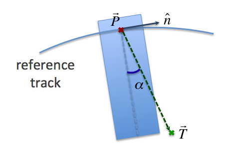
The LLH file is created by ground projecting each SLC pixel from slant range to ground range by iterating to find the platform vector P using the following formula:

where T is the target location vector, P is the platform location vector, n is the unit vector normal to the image plane, and α is the steering angle according to the following diagram:
-
The LKV file is created by subtracting the platform vector from the target vector found in the above process, then transform to ENU (east, north, up) coordinates.
Data format description
-
SLC data:
The SLC is a pure binary file (complex floating-point, 8 bytes per pixel) with no header bytes. The number of lines and samples are entered in the annotation file as "slc_#_#x# Rows" and "slc_#_#x# Columns" respectively. There is a separate file for each segment and polarization (HH, HV, VH, and VV) of the acquisition. The pixel spacing in meters is given in the annotation file by "SLC Azimuth Pixel Spacing" for the azimuth direction and "SLC Range Pixel Spacing" for the range direction. The projection of the data is in the natural slant range projection. The geographic coordinates of the data are defined by the peg latitude, longitude and heading, and by the cross track and along track offset of the upper left pixel (given by "Image Starting Slant Range" and "Segment # Data Starting Azimuth" in the annotation file). The byte order is little endian. The units of the data are linear radar amplitude (rather than db units).
The complex SLC files for a particular polarization correspond to the appropriate measurement of the scattering matrix:
Shh
Shv
Svh
Svv
-
LLH data:
There is one .llh file per segment of the stack. This file is a pure binary file with no header bytes. It is in floating point format, with 12 bytes per pixel (4 bytes for latitude, 4 bytes for longitude, 4 bytes for height). The byte order is little endian.
-
LKV data:
There is one .lkv file per segment of the stack. This file is a pure binary file with no header bytes. It is in floating point format, with 12 bytes per pixel (4 bytes for east, 4 bytes for north, 4 bytes for up). The byte order is little endian.
-
DOP data:
There is one .dop file for a stack. This file is in ASCII format consisting of two columns. The first column is the radar range in meters and the second column is the doppler in radians/meter. Each row correspond to a different range in the 1x1 SLC image.
-
Annotation file:
The annotation file (.ann) is a keyword/value ASCII file in which the value on the right of the equals sign corresponds to the keyword on the left of the equals sign. The number of keywords may change with time, so the line number should not be assumed to be constant for any given keyword. In addition, the spacing between keywords and values may change. The units are given in parenthesis between the keyword and equal sign, and may change from annotation file to annotation file and within each annotation file. Comments are indicated by semicolons (;), and may occur at the beginning of a line, or at the middle of a line (everything after the semicolon on that line is a comment). The length of each text line is variable, and ends with a carriage return. There may be lines with just a carriage return or spaces and a carriage return.
Calibration of the data:
Please see the calibration page for documentation on calibration of the data.