
Polarimetric (PolSAR) Data Format
UAVSAR data format for polarimetric products
The format of the following files are described:
- SLC files (.slc): calibrated single look complex files for each polarization (HH, HV, VH, and VV), floating point format, little endian, 8 bytes per pixel, corresponding to the scattering matrix in sigma0.
- MLC files (.mlc): calibrated multi-looked cross products, floating point format, three files 8 bytes per pixel, three files 4 bytes per pixel, little endian.
- Compressed Stokes Matrix product (.dat): AIRSAR compressed stokes matrix format for software compatibility (http://airsar.jpl.nasa.gov/data/data_format.pdf). 10 bytes per pixel.
- Ground projected files (.grd): calibrated complex cross products projected to the ground in simple geographic coordinates (latitude, longitude). There is a fixed number of looks for each pixel. Floating point, little endian, 8 or 4 bytes per pixel.
- Hgt file: the DEM that the imagery was projected to, in the same geographic coordinates as the ground projected files. Floating point (4 bytes per pixel), little endian, ground elevation in meters.
- Annotation file (.ann): a text file with metadata. Example
- Terrain slope file (.slope): The terrain slope file (.slope) contains the derivatives of the digital elevation model (DEM) in the East and North direction. The file is an array of two interleaved floating point numbers (2 x 4 bytes per pixel) with geometry identical to the other ground-projected data layers (.grd, .hgt, .inc). For each interleaved pixel, the first 4 byte value is the terrain slope in the east direction, and the second 4 byte value is the slope in the north direction. Floating point, little endian.
-
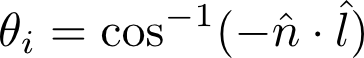
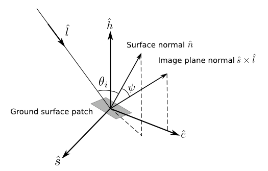
Incidence angle file (.inc): the local incidence angle, the angle between the surface normal and the radar line of site. The file consists of 4-byte floating point values, coregistered with the slope file. The floating point, little endian file contains values reported in radians:
File Naming Convention
Each filename consists of the following components, separated by underscores:
- Six character abbreviation for the desired target site (image may contain other sites).
- Three digits aircraft heading followed by a incremented alphanumeric counter (this is set during flight planning).
- Five digits in which the first two digits are the last two digits of the year of the UAVSAR flight, and the next three digits are the flight number by UAVSAR counted sequentially from the first flight of the year.
- Three digits indicating which flight line of the flight this acquisition was from, counted sequentially from the beginning of the flight.
- Six digits in which the first two digits are the last two digits of the year of the UAVSAR flight, the next two digits are the month the acquisition was acquired, and the last two digits are the day of the month of the acquisition (UTC).
- Between 6 and 8 characters, a single character indicating the frequency band, followed by the steering angle (three digits) followed by the polarization. The polarization may be between 2 characters (first character is the transmit polarization, and second character is the receive polarization) and 4 characters (if the file represents a cross product).
- Two characters indicating whether cross talk has been calibrated or not. XX - no cross talk calibration. CX - cross talk calibration has been applied.
- Two digits indicating the processing version number.
-
Three digit file extension indicating the data type. For example:
Dthvly_34501_08038_006_080731_L090HH_XX_01.slc
where Dthvly is the site name, 345 degrees is the heading of UAVSAR in flight, with a counter of 01, the flight was the thirty-eighth flight by UAVSAR in 2008, this data take was the sixth data take during the flight, the data was acquired on July 31, 2008 (UTC), the frequency band was L-band, pointing at perpendicular to the flight heading (90 degrees counterclockwise), this file contains the HH data, this is the first interation of processing, cross talk calibration has not been applied, and the data type is SLC.
Data format description
-
SLC data:
The SLC is a pure binary file (complex floating-point, 8 bytes per pixel) with no header bytes. The number of lines and samples are entered in the annotation file as slc_amp.set_rows and slc_amp.set_cols respectively. There is a separate file for each polarization channel (HH, HV, VH, and VV). The pixel spacing in meters is given in the annotation file by slc_amp.row_mult and slc_amp.col_mult for the azimuth and range directions, respectively. The projection of the data is in the natural slant range projection. The geographic coordinates of the data are defined by the " Peg position and heading ", and by the cross track and along track offset of the upper left pixel (given by set_plat, set_plon, and set_phdg, and slc_amp.row_addr and slc_amp.col_addr in the annotation file). The byte order is little endian. The units of the data are linear radar amplitude (rather than dB units).
The four complex SLC files correspond to the measurement of the scattering matrix:
Shh
Shv
Svh
Svv
-
MLC data:
The MLC is a pure binary file with no header bytes. Three of the files are complex floating point, 8 byte per pixel. These complex products are derived from the average (usually 3 pixels in range, and 12 pixels in azimuth, given precisely by " Number of Range Looks in MLC " and "Number of Azimuth Looks in MLC" in the annotation file) of the product of each SLC pixel and correspond to:
ShhShv*
ShhSvv*
ShvSvv*
Three of the files are real floating point, 4 bytes per pixel. These real powers are derived from the average (usually 3 pixels in range, and 12 pixels in azimuth, given precsely by " Number of Range Looks in MLC " and "Number of Azimuth Looks in MLC" in the annotation file) of the product of each SLC pixel and correspond to:
ShhShh*
ShvShv*
SvvSvv*
The number of lines and samples are entered in the annotation file as mlc_mag.set_rows and mlc_mag.set_cols respectively. There is a separate file for each product (HHHH, HVHV, VVVV, HHHV, HHVV, HVVV). The pixel spacing in meters is given in the annotatipon file by mlc_mag.row_mult and mlc_mag.col_mult for the azimuth and range directions, respectively. The projection of the data is in the natural slant range projection. The geographic coordinates of the data are defined by the "Peg position and heading", and by the cross track and along track offset of the upper left pixel (given by set_plat, set_plon, and set_phdg, and mlc_mag.row_addr and mlc_mag.col_addr in the annotation file). The byte order is little endian. The units of the data are linear radar power (rather than dB units).
-
GRD data:
The grd files consists of three real floating point, 4 bytes per pixel, and three complex floating point, 8 bytes per pixel files. The number of lines and samples may be found in the annotation file and are given by grd_mag.set_rows and grd_mag.set_cols respectively. The grd files contain projected multi-looked data for crossproducts HHHH, HVHV, VVVV, HHHV, HVHV, and HVVV:
ShhShv*
ShhSvv*
ShvSvv*
ShhShh*
ShvShv*
SvvSvv*
in linear power units rather than db. The byte order is little endian. The data is in an equiangular coordinate system in which each line and pixel increments in latitude and longitude by grd_mag.row_mult and grd_mag.col_mult degrees from the upper left corner coordinate given by grd_mag.row_addr and grd_mag.col_addr
UAVSAR projects slant range images to ground range using the backward projection method. An equiangular grid is found with latitude and longitude boundaries that cover the entire slant range image. For each point on the ground range grid, the corresponding indices are calculated on the multilooked slant range image. The data value closest to the coordinates pointed by the calculated slant range indices is assigned to the point on the ground range grid.
These files are co-registered to the HGT file.
-
HGT data:
The height file is a pure binary real*4 floating point file where the number of lines and samples may be found in the annotation file and are given by hgt.set_rows and hgt.set_cols respectively. This height file contains the values of elevation used to project the slant range data to the Earth's surface. The value of the ground elevation is given in meters. The datum is given by "DEM Datum" in the annotation file. The source of the DEM is given by "DEM source" in the annotation file. The data is in an equiangular coordinate system in which each line and pixel increments in latitude and longitude by hgt.row_mult and hgt.col_mult degrees from the upper left corner coordinate given by hgt.row_addr and hgt.col_addr
This file is co-registered to the GRD files.
-
Annotation file:
The annotation file (.ann) is a keyword/value ASCII file in which the value on the right of the equals sign corresponds to the keyword on the left of the equals sign. The number of keywords may change with time, so the line number should not be assumed to be constant for any given keyword. In addition, the spacing between keywords and values may change. The units are given in parenthesis between the keyword and equal sign, and may change from annotation file to annotation file and within each annotation file. Comments are indicated by semicolons (;), and may occur at the beginning of a line, or at the middle of a line (everything after the semicolon on that line is a comment). The length of each text line is variable, and ends with a carriage return. There may be lines with just a carriage return or spaces and a carriage return.
When using mdx to display the data files, use the corresponding display parameters in the annotation file. Use mlc_pwr to display the three real (4 byte per pixel) MLC data: HHHH, HVHV, and VVVV. Use mlc_mag and mlc_phase to display the three complex (8 byte per pixel) MLC data: HHHV, HHVV, and HVVV. Similarly, use grd_pwr to display real (4 byte per pixel) GRD data. Use grd_mag and grd_phase to display complex (8 byte per pixel) GRD data.
-
KML/KMZ file:
The kml/kmz files are representations of the GRD data in Keyhole Markup Language. These files can be displayed in applications like Google Maps and Google Earth. The kml files contain low resolution image while the kmz files contain full resolution image (when zoomed in). The PolSAR kml/kmz files use the following color code:
Red - ShhShh*
Green - ShvShv*
Blue - SvvSvv*
Calibration of the data:
Please see the calibration page for documentation on calibration of the data.